
Here is the schematic. I'll make new circuits, cutting at the red lines. 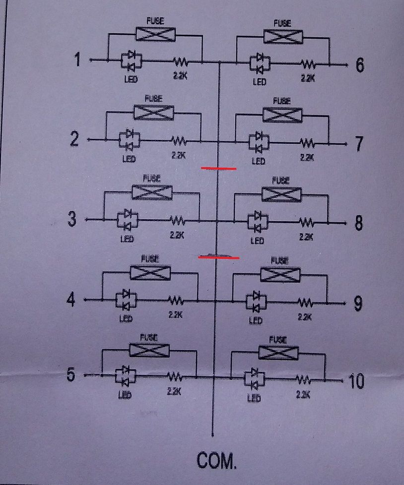
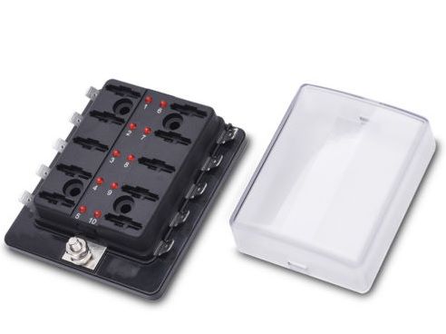
with the internals exposed. The cover is just held in place by tabs, and they easily release. 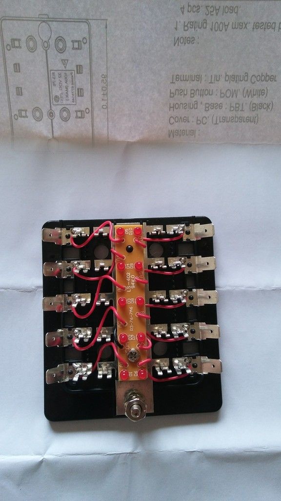
The power bar removed. I had to unsolder the black wire that supplied power to the LED's.
I'll cut at the red lines and I added mounting holes where the blue circles are. 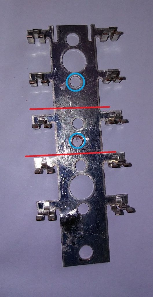
before cutting I reinstalled it so I could transfer the new holes to the base. 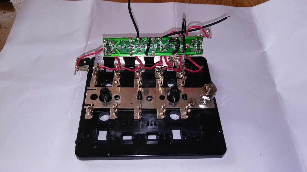
The main power was fed around the perimiter of the circuit board. I severed it at the red X's to create my three circuits for the LED's. Then I jumpered the power, indicated by the blue. Power was supplied to the board from each section at the yellow circles.
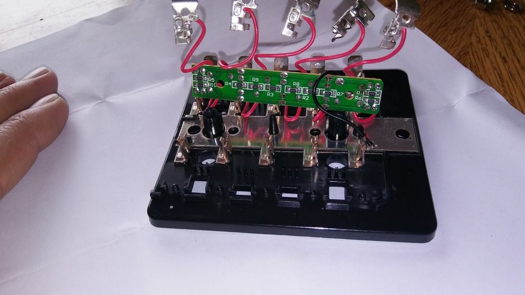
You can see the power strip cut and each section bolted into place. 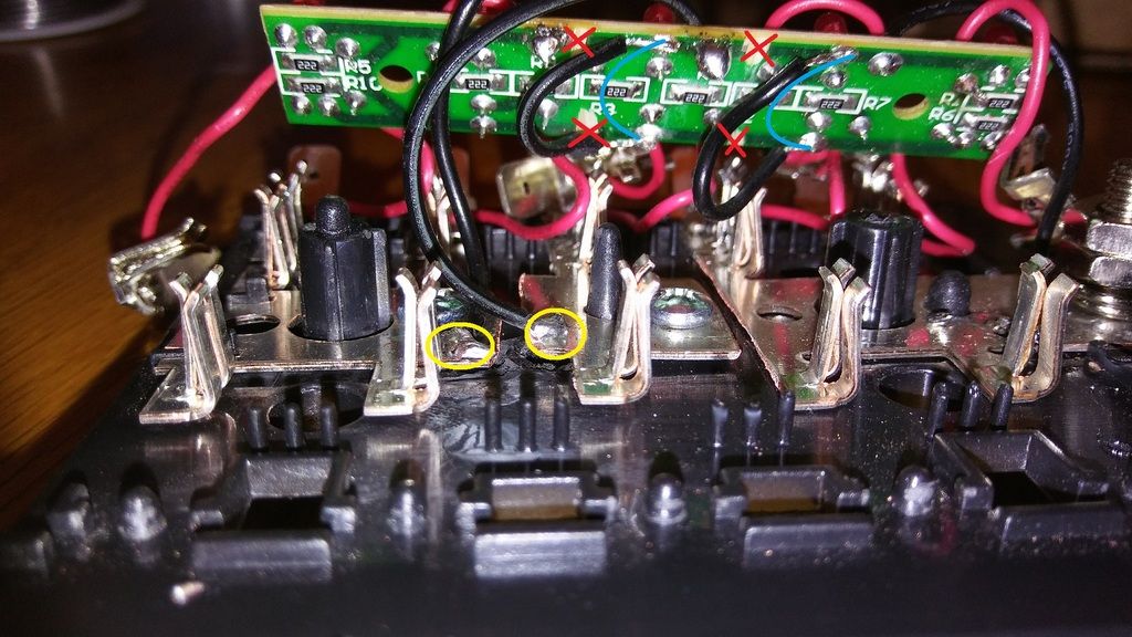
With the circuit board back in place. I attached supply wire to the power strips. Red for the top 4, black for the middle 2. 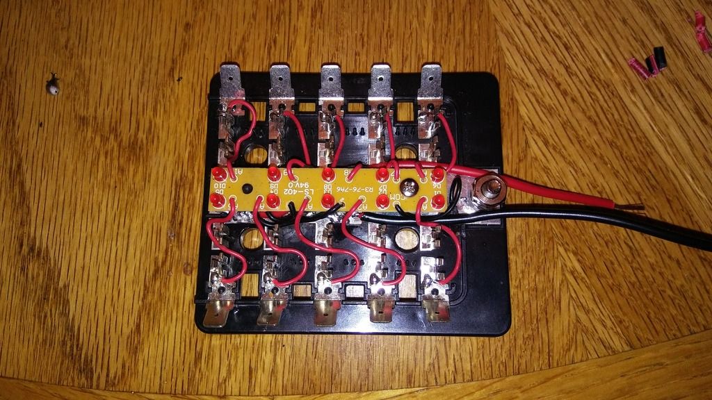
I added connection terminals to all three.
Testing it here. With a good fuse inline the LED does not light. 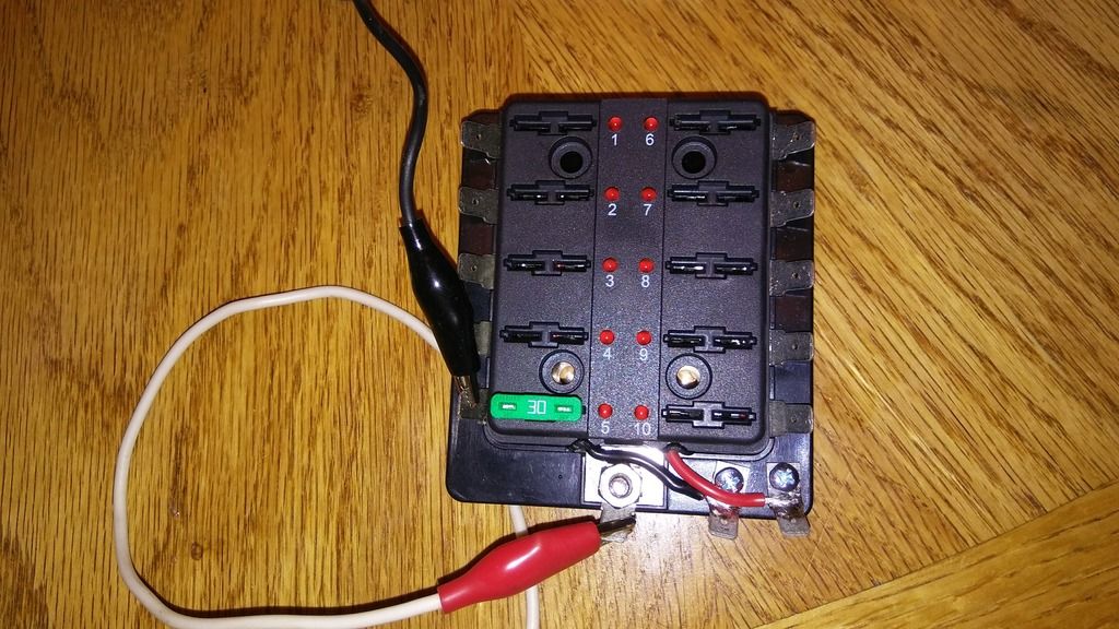
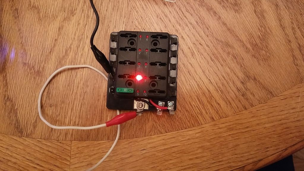
And with an open, the LED lights. I tested all points, and it works as intended. 
and the final product. Not too shabby.
The question now is, how to mount it. Do I replace the OEM block or mount it under the dash and leave the OEM block in place, but unpowered and keep the stock look? Time will tell. 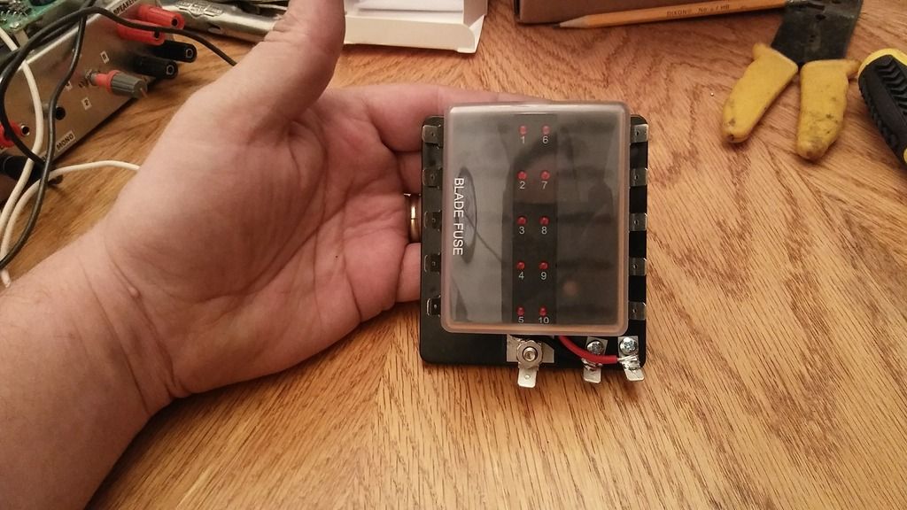

Responses